This is MicroTCA!
MicroTCA defines compact backplane-based computer systems based on AdvancedMC (AMC) modules. MicroTCA systems are used in industry, research, medical technology, traffic engineering, defense technology, telecommunications and network technology.
Extremely scalable systems
The MicroTCA specification defines high scalable systems – from simple low-cost systems to highly accessible carrier grade computer architectures. Depending on the package form, up to 12 AMC modules are possible in one package. Multiple packages can be easily
coupled with each other. Modules with any function can be used in each slot. Of course, any operating system and processor architecture can be used. In a MicroTCA system, in addition to the AMC modules, there is at least one MicroTCA Carrier Hub (MCH) and at least one Power Module (PM).
Originally intended only for telecommunications applications, MicroTCA systems have now found their way into many areas. The AMC modules communicate with each other via switched fabrics. Ethernet (1GbE, 10GbE, 40GbE), PCI Express, RapidIO, SATA and SAS are defined as possible protocols. AMC modules are available in different front panel widths and optionally also with double board size.
MicroTCA Carrier Hub
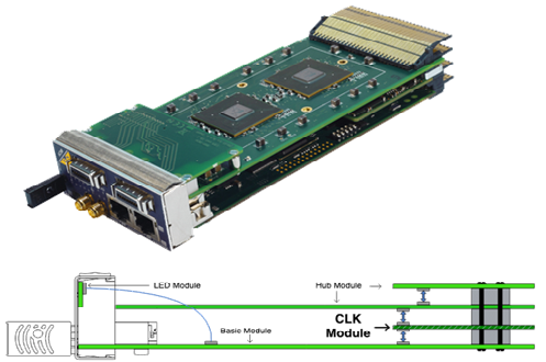
The MCH defines the connections, monitors the complete system and generates the system clocks. It also monitors and manages the AMC modules, up to 4 Power Modules (PM), and 2 Cooling Units (CU). It provides the required switch functionality. The MCH has the design of an AMC module, but consists of multiple PCBs and has a dedicated slot in the system. For fail-safe systems, two MCHs can be used redundantly in one system. Furthermore, the MCH provides an Ethernet port as a management interface with extensive possibilities.
MTCA .4
The MTCA.4 specification describes the extensions to the MTCA standard that the high energy physics research institutes
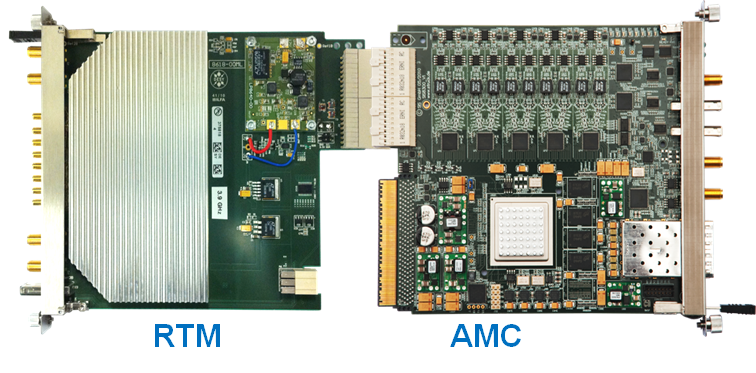
require for their applications. In addition to the specification of a unified board format (Double Mid-Size), so-called Rear-Transition Modules (μRTM) have also been redefined. Among other things, this allows the conversion and signal conditioning sections to be decoupled from the data processing section. The larger board area also allows more complex board designs for high-performance analog/digital converters to be implemented.
An additional backplane allows latency-free communication between high-performance FPGA modules.
Of course, AMC.0 compatible modules can also be used in MTCA.4 systems, for which corresponding splitter kits are available. Due to this modularity and the larger board area, these systems can also be used in many other fields of application outside of research and are used successfully there.
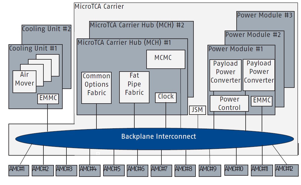
MicroTCA System Block Diagram
MicroTCA combines serial high-speed links, system monitoring, efficient cooling and redundancy concepts in one industrial standard.
standard.
This standard includes a backplane-based system with a central monitoring unit, MicroTCA Carrier Hub (MCH), 1-2 fan units (CU), up to 4 power supplies (PM) and a maximum of 12 AdvancedMC modules (AMC).
When the system is powered up, the PM, CU and MCH power up. After the MCH initializes, it takes control of the PM, regulates the CUs, and checks the AMC modules present.
If the information from the AMC modules is correct, it switches the high-speed links between the modules (fat pipe). If sufficient power is available in the system, the MCH switches on the payload power of the individual AMC modules.


